Precision Modal Testing: Capturing Reliable Data
Modal testing plays a critical role in accurately identifying a structure’s natural frequencies, mode shapes, and damping ratios. These parameters provide quantitative vibration performance data across the entire lifecycle of a product—from design and validation to operation and maintenance. As a core technique for solving structural vibration problems, modal testing is widely applied in aerospace, automotive, machinery, civil engineering, and other high‑performance engineering fields.
Why Modal Testing Matters
The objective of modal testing is to obtain highly accurate dynamic characteristics of a structure, enabling engineers to:
- Optimize structural design and material selection
- Prevent resonance during operation
- Improve stiffness‑to‑weight ratios
- Validate simulation and finite element models
- Detect early‑stage structural damage or degradation
Accurate vibration data is the foundation of trustworthy modal analysis—and sensor selection plays a decisive role in data quality.
Key Application Areas of Modal Testing
1. Structural Design & Optimization
In aerospace, automotive, shipbuilding, and mechanical engineering, modal parameters are used during new product development to refine geometry, materials, and reinforcement layouts. This helps avoid resonance while reducing mass and improving structural rigidity.
2. Fault Diagnosis & Structural Health Monitoring
By comparing modal parameters of a structure in healthy and in‑service conditions, engineers can identify issues such as cracks, loose joints, and fatigue damage. This approach is widely used for wind turbine blades, bridges, machine tools, and other critical assets.
3. Vibration Control
Modal data enables targeted design of vibration isolation and damping solutions—such as dampers or tuned mass absorbers—to suppress specific vibration modes, reduce noise, and improve both equipment accuracy and operator comfort.
4. Model Validation (FEA Correlation)
Experimental modal testing is essential for validating finite element analysis (FEA) models. Test data is used to refine boundary conditions and material properties, significantly improving simulation accuracy.
5. Product Reliability Testing
In industrial quality assurance, modal testing evaluates a product’s resistance to vibration and shock, ensuring stable performance during transportation and real‑world operation.
Comparison of Common Modal Excitation Methods
1. Impact Hammer Excitation
Principle: A handheld hammer strikes the structure while an integrated force sensor records the input force.
Advantages: – Simple operation and low cost – Minimal added mass—ideal for small or lightweight structures – Fast multi‑point excitation
Limitations: – Limited excitation energy, especially at low frequencies – Force signal depends on operator technique – Frequency range limited by hammer tip material
Typical Applications: – On‑site testing of small equipment – Preliminary modal surveys – Scenarios where shakers cannot be installed
Selection Considerations: – Hammer tip material (soft rubber for low frequency, steel for high frequency) – Force sensor range and sensitivity
2. Electrodynamic Shaker Excitation
Principle: A signal generator and power amplifier drive a shaker to produce controlled steady‑state or transient excitation.
Advantages: – Stable, repeatable excitation – Supports sine sweep, random, and broadband inputs – High measurement accuracy
Limitations: – Higher system cost – More complex installation and setup – Added mass can influence small or lightweight structures
Typical Applications: – Laboratory modal testing of large structures – High‑precision and highly repeatable measurements – Accurate frequency response function (FRF) testing
Selection Considerations: – Excitation force range – Frequency bandwidth – Contact vs. non‑contact mounting
3. Ambient (Operational) Excitation
Principle: Natural environmental inputs—such as wind, traffic, machinery operation, or micro‑seismic motion—excite the structure.
Advantages: – No artificial excitation required – Does not interfere with normal operation – Ideal for structures where artificial excitation is not allowed
Limitations: – Excitation is uncontrollable and environment‑dependent – Requires long acquisition times – Data processing is more complex
Typical Applications: – Bridges and large civil structures – Online modal analysis of rotating machinery – Sensitive structures where external excitation is prohibited
Selection Considerations: – Sensors with low noise and wide bandwidth – High sensitivity to capture low‑energy excitation
LNS Equipment Selection Recommendations
1. Small Equipment & On‑Site Testing
Recommended Configuration: Impact hammer + miniature modal accelerometers
LNS N03B00 Impact Hammer
The N03B00 integrates a precision force sensor directly into the striking surface and includes built‑in IEPE circuitry for accurate force measurement. Multiple interchangeable hammer tips are available. The external BNC output ensures easy cable integration and stable signal transmission.
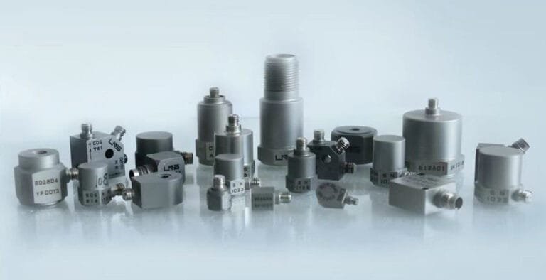
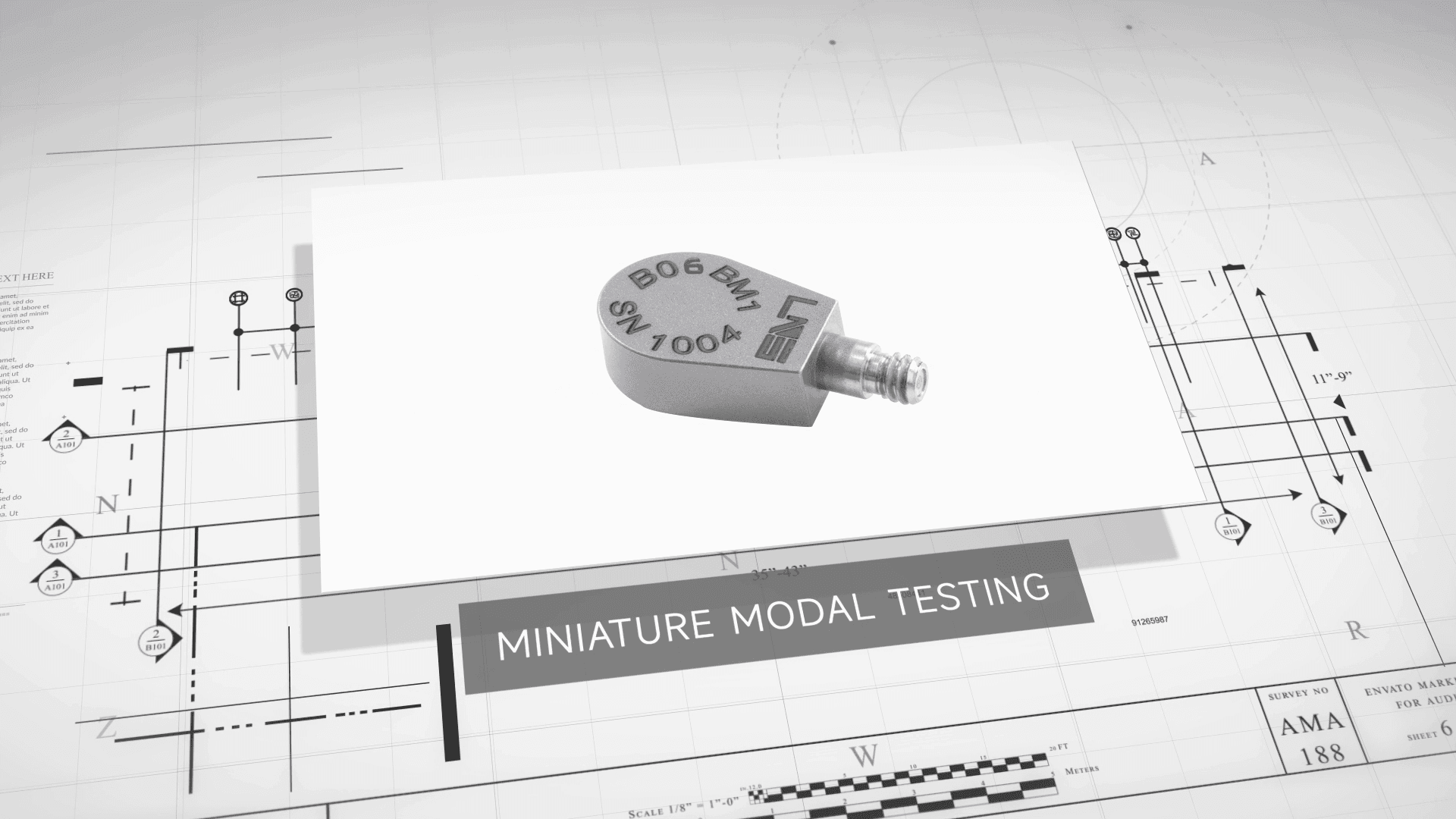
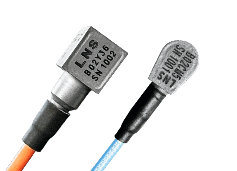
Miniature Modal Accelerometers
LNS offers a range of miniature single‑axis and triaxial accelerometers designed specifically for modal testing. Features include: – Integrated miniature IEPE electronics – Low noise and excellent dynamic performance – Wide frequency response (0.5–14 kHz) – Excellent phase consistency (≤ ±1° within the same batch) – Ultra‑low mass (as low as 0.35 g) – Shape‑memory alloy mounting hardware for long‑term stability – Multiple sensitivities, ranges, and mounting options
These characteristics ensure accurate FRF calculation, high repeatability, and reliable multi‑point measurements.
2. Large Structures & High‑Precision Laboratory Testing
Recommended Configuration: Shaker system + wide‑band piezoelectric accelerometers
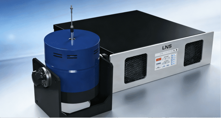
LNS Shaker Systems
LNS shaker systems consist of power amplifiers, shakers, and force sensors. The digital low‑noise amplifier design provides high efficiency and includes real‑time monitoring of output current, voltage, and temperature. Comprehensive protection features—such as power‑on delay, emergency shutdown, DC offset protection, and short‑circuit protection—ensure long‑term reliability.
Shakers are available with multiple force ratings and are portable and easy to operate.
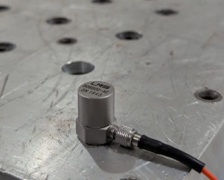
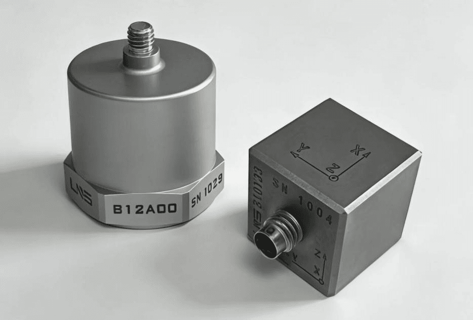
Wide‑Band Piezoelectric Accelerometers
LNS wide‑band triaxial accelerometers are the core sensors for modal response acquisition. Key benefits include: – Broad frequency coverage (0.5–11 kHz) – Minimal added mass – Multiple sensitivities, ranges, and mounting options – High phase consistency – Low transverse sensitivity to minimize cross‑axis interference
3. Bridges, Buildings & Large Civil Structures
Recommended Configuration: Low‑frequency, high‑sensitivity accelerometers
LNS low‑frequency accelerometers are specifically designed for modal testing of large structures such as bridges, buildings, and foundations. Key performance characteristics include:
- Ultra‑low frequency response down to 0.1 Hz
- Extremely low noise with high resolution (up to 0.000001 g)
- Small measurement ranges optimized for ambient excitation (e.g., 0.5 g)
- Easy installation and strong immunity to environmental interference
These sensors are well suited for both ambient and controlled excitation scenarios, delivering reliable data even under very low vibration levels.
Conclusion
Accurate modal testing starts with the right sensors. From lightweight structures to massive civil infrastructure, LNS offers a comprehensive portfolio of accelerometers, impact hammers, and shaker systems designed to capture every subtle vibration. With low noise, excellent phase consistency, and application‑specific designs, LNS solutions help engineers generate more reliable modal data—and make better engineering decisions with confidence.