Sensor Model Numbering Guide
Our part numbering system provides a clear, standardized way to identify key sensor characteristics at a glance. Each character in the six-digit code conveys specific performance and mechanical information.
Use the breakdown below to quickly understand any LNS sensor model.
1. First Digit – Sensor Type
Indicates the sensing technology or function.
| Code | Sensor Type |
|---|---|
| 2 | TEDS-Enabled Sensor |
| A | MEMS Accelerometer |
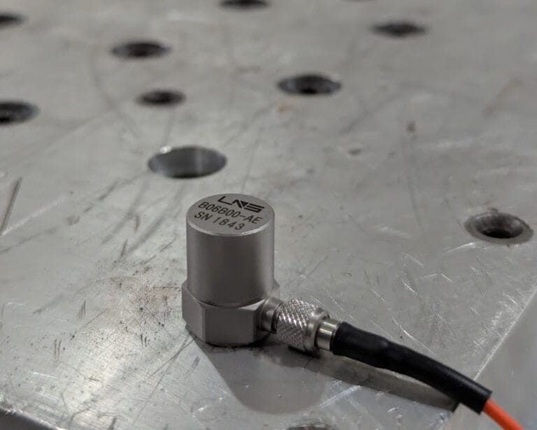
| B | IEPE Accelerometer |
| C | Charge-Type Accelerometer |
| D | Dynamic Force Sensor |
| F | Pressure Sensor |
2. Second & Third Digits – Sensitivity Rating
Defines the nominal sensitivity of the sensor.
| Code | Sensitivity |
|---|---|
| 01 | 5 mV/g |
| 02 | 10 mV/g |
| 03 | 20 mV/g |
| 05 | 50 mV/g |
| 06 | 100 mV/g |
| 09 | 500 mV/g |
| 10 | 1000 mV/g |
3. Fourth Digit – Connector Orientation
Specifies the connector location or configuration.
| Code | Connector Type |
|---|---|
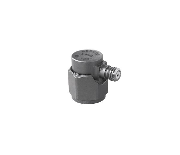
| A | Top-Exit Connector |
| B | Side-Exit Connector |
| Y | Triaxial Connector Configuration |
4. Fifth & Sixth Digits – Sensor Series / Mechanical Design
Defines the mechanical form factor or special application category.
| Code | Mechanical Design / Series |
|---|---|
| 3X | Triaxial Cube Design |
| 4X | Through-Hole / Stud-Mount Series |
| 5X | Industrial Series |
| 7X | Waterproof Series |
| 9X | High-Temperature Series |
Example
B06A53
- B → IEPE accelerometer
- 06 → 100 mV/g sensitivity
- A → Top-exit connector
- 53 → Industrial series